Alternating Current
How AC circuits behave with resistors, inductors, and capacitors — power transmission and resonance
Table of Contents
7.1 Introduction
We have so far considered direct current (dc) sources and circuits with dc sources. These currents do not change direction with time. But voltages and currents that vary with time are very common. The electric mains supply in our homes and offices is a voltage that varies like a sine function with time. Such a voltage is called alternating voltage (ac voltage) and the current driven by it in a circuit is called the alternating current (ac current).
7.2 AC Voltage and Current
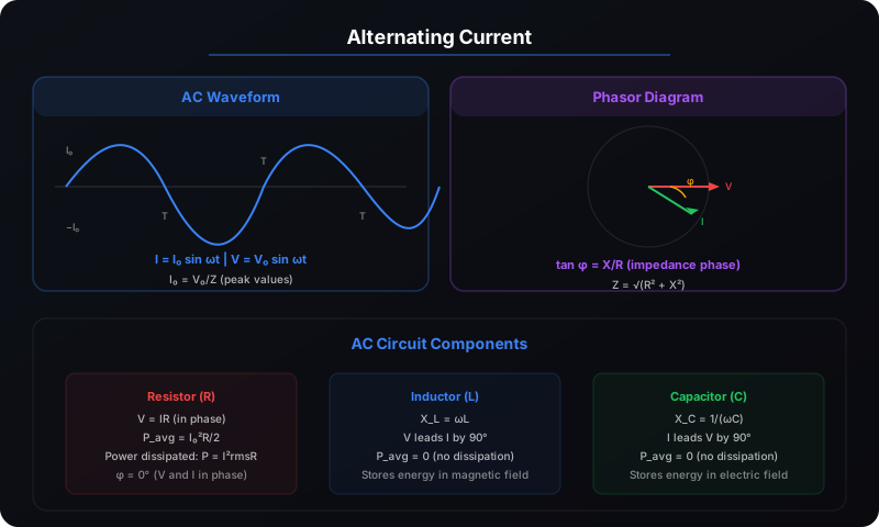
An alternating voltage varies sinusoidally with time:
The root-mean-square (rms) values are used for AC measurements:
7.3 Phasor Diagrams
A phasor is a rotating vector that represents an AC quantity. Its length represents the amplitude and its angular position represents the phase. Phasors simplify the analysis of AC circuits with multiple components.
7.4 AC Circuit with Resistor
7.5 AC Circuit with Inductor
7.6 AC Circuit with Capacitor
7.7 Series LCR Circuit
The series LCR circuit combines resistance, inductance, and capacitance. The impedance is:
Resonance occurs when X_L = X_C, i.e., ωL = 1/(ωC). At resonance: Z = R (minimum), I = I₀ (maximum), ω₀ = 1/√(LC), Q-factor = ω₀L/R.
7.8 Power in AC Circuits
The average power dissipated in an AC circuit is:
7.9 LC Oscillations
An LC circuit (no resistance) oscillates energy between the electric field of the capacitor and the magnetic field of the inductor:
7.10 Transformers
A transformer changes AC voltage levels using mutual induction between two coils:
- Step-up transformer: Increases voltage, decreases current (used in power transmission)
- Step-down transformer: Decreases voltage, increases current (used in household supply)
- Efficiency: η = P_out/P_in × 100% (typically 95-99% for large transformers)